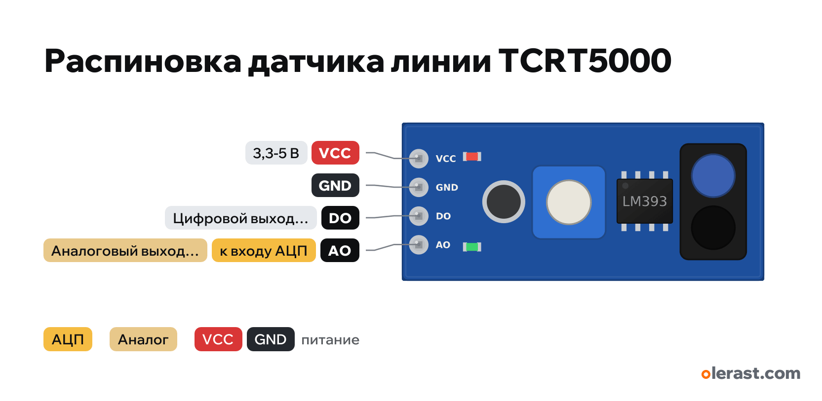
TCRT5000 line and edge sensor with LM393 pinout
TCRT5000 line and edge sensor with LM393 (4 pins), Vishay TCRT5000 and LM393 comparator, 5 V logic, 32×14 mm, 4 pins
partly verified17.10.2026
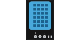
Top view, header on the left, sensor on the right (facing down).
Download PNG- Chip
- Vishay TCRT5000 and LM393 comparator
- Logic
- 5 V
- Power
- VCC 3.3-5 V
Important
- The sensor faces down 2–10 mm above the surface: a black line barely reflects IR, a white one does.
- Set the DO threshold with the trimmer while watching the LED.
- Works the same for a sumo robot (table edge) and for a line; in sunlight and under an incandescent lamp the IR background shifts the threshold.
- Geometry from KiCad footprints and photos (±0.5 mm). Holes and small components are approximate, check with calipers.
All pins
| Label | Number | Functions | Limits | Check |
|---|---|---|---|---|
| VCC | 5 V | power input | not from manufacturerA module with no manufacturer: the order is from seller descriptions, newer batches differ (VCC, DO, AO, GND). Size and components from photos, not dimensioned. | |
| GND | Ground | not from manufacturerA module with no manufacturer: the order is from seller descriptions, newer batches differ (VCC, DO, AO, GND). Size and components from photos, not dimensioned. | ||
| DO | not from manufacturerA module with no manufacturer: the order is from seller descriptions, newer batches differ (VCC, DO, AO, GND). Size and components from photos, not dimensioned.The threshold is set by the trimmer, the second LED lights when triggered. The level on reflection differs between batches: check by the LED.Pull-up to VCC: at 5 V supply the output is 5 V, for an ESP32 power the module from 3.3 V.Labelled on other revisions as: D0, OUT | |||
| AO | Phototransistor analog outputto an ADC input | not from manufacturerA module with no manufacturer: the order is from seller descriptions, newer batches differ (VCC, DO, AO, GND). Size and components from photos, not dimensioned.Labelled on other revisions as: A0 |
Sources
Not verified against the manufacturer: 4 of 4 pins. The pin card says what confirms each one and where sources disagree.
- Vishay TCRT5000 datasheet (Rev 1.7)datasheet, checked 17.10.2026package 10.2×5.8×7, top view: phototransistor (C, E) and IR LED (A, C), forward current up to 60 mA, best range 2.5 mm (0.2–15 mm)
- TI LM393 datasheetdatasheet, checked 17.10.2026comparator with open-collector output, supply 2–36 V
- Robu: TCRT5000 line tracking sensorthird-party source, checked 17.10.2026order VCC, GND, D0, A0; newer batches may have VCC, D0, A0, GND
- Soldered: TCRT5000, how it worksthird-party source, checked 17.10.2026The LM393 compares the phototransistor voltage with the trimmer threshold, digital and analog outputs
Size: about 32×14 from seller photos, not dimensioned (approximate).
FAQ
- What supply voltage does the TCRT5000 line and edge sensor with LM393 need?
- VCC: 3.3-5 V. 5 V logic.