ESP8266 NodeMCU V3 LoLin pinout
NodeMCU v3 LoLin (CH340G), ESP8266EX, 3.3 V logic, 31×58 mm, 30 pins
partly verified15.10.2026
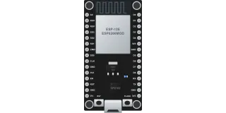
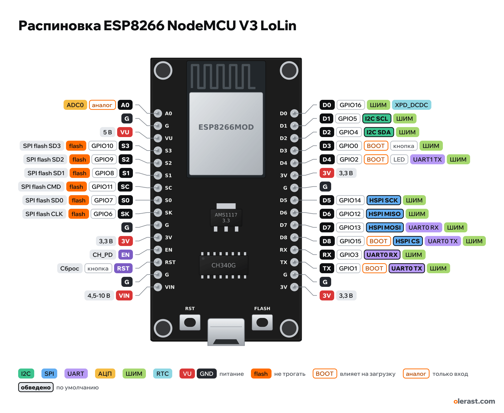
Top view, USB at the bottom, module antenna at the top.
BuyCompareDownload PNG- Chip
- ESP8266EX, ESP-12E/F (ESP8266MOD)
- Logic
- 3.3 V
- Power
- Micro-USB 4.75-5.25 VVIN 4.5-10 VVU
- Defaults in ESP8266 Arduino core (NodeMCU 1.0)
- I2C: SDA 4, SCL 5SPI: MOSI 13, MISO 12, SCK 14, SS 15UART: TX 1, RX 3LED: 2
Which ESP8266 NodeMCU V3 LoLin pins are safe to use
Free to use
GPIO3-5, GPIO12-14, GPIO16
Use with care
- GPIO0, GPIO2, GPIO15: strapping: the level at power-up selects the boot mode.
- GPIO1: signal at boot.
- A0: analog input only.
Leave alone
- GPIO6-11: flash and PSRAM memory.
Important
- 3.3 V logic, do not apply 5 V to a GPIO (the datasheet VIH limit is 3.6 V).
- Boot: GPIO15 (D8) = 0, GPIO2 (D4) = 1, GPIO0 (D3) = 1 runs from flash; GPIO0 = 0 is firmware download mode. Do not connect anything to these pins at power-up that pulls them the wrong way.
- Interrupts on all GPIO except GPIO16 (D0). Software PWM on GPIO0–16.
- To wake from deep sleep, connect D0 (GPIO16) to RST.
- Wide board: the rows are 1.1 inch (27.94 mm) apart, so no free holes are left on a standard breadboard.
- S0–S3, SC, SK are the flash pins (GPIO6–11): do not use.
- The position of the first pin was measured from a photo (±1 mm). Holes and small components are drawn approximately.
Revisions and clones
- Different LoLin batches have a different regulator and mask color. Boards on the CP2102 with the same width exist.
- The "NodeMCU v3 CH340" schematic found online actually repeats the v2 schematic on the CP2102.
All pins
| Label | Number | Functions | Limits | Check |
|---|---|---|---|---|
| A0 | TOUT, Arduino A0 | ADC0 (A0), 10 bit | analog input onlynot 5 V tolerantonboard voltage divider | not from manufacturerWhether the LoLin has a divider on A0 is not verified against a schematic (no manufacturer schematic).On the chip itself the range is 0–1.0 V. Boards add a divider, which widens the range (see the board note).The on-board divider is expected to be as on the NodeMCU v2 (0–3.2 V), but not verified against documentation. |
| G | Ground | not from manufacturerThe LoLin has no manufacturer documentation: labels are from photos, dimensions from a user measurement. The D pin assignment matches the NodeMCU (nodemcu variant in the Arduino core). | ||
| VU | 5 V | power output | not from manufacturerThe LoLin has no manufacturer documentation: labels are from photos, dimensions from a user measurement. The D pin assignment matches the NodeMCU (nodemcu variant in the Arduino core).5 V from USB (in the place of RSV on the v2). | |
| S3 | GPIO10 | SPI flash SD3 | not 5 V tolerantused by flash, do not use | not from manufacturerThe LoLin has no manufacturer documentation: labels are from photos, dimensions from a user measurement. The D pin assignment matches the NodeMCU (nodemcu variant in the Arduino core).Connected to the module flash. Do not use.S3 = GPIO10. |
| S2 | GPIO9 | SPI flash SD2 | not 5 V tolerantused by flash, do not use | not from manufacturerThe LoLin has no manufacturer documentation: labels are from photos, dimensions from a user measurement. The D pin assignment matches the NodeMCU (nodemcu variant in the Arduino core).Connected to the module flash. Do not use.S2 = GPIO9. |
| S1 | GPIO8 | SPI flash SD1 | not 5 V tolerantused by flash, do not use | not from manufacturerThe LoLin has no manufacturer documentation: labels are from photos, dimensions from a user measurement. The D pin assignment matches the NodeMCU (nodemcu variant in the Arduino core).Connected to the module flash. Do not use.S1 = GPIO8. |
| SC | GPIO11 | SPI flash CMD | not 5 V tolerantused by flash, do not use | not from manufacturerThe LoLin has no manufacturer documentation: labels are from photos, dimensions from a user measurement. The D pin assignment matches the NodeMCU (nodemcu variant in the Arduino core).Connected to the module flash. Do not use.SC = GPIO11. |
| S0 | GPIO7 | SPI flash SD0 | not 5 V tolerantused by flash, do not use | not from manufacturerThe LoLin has no manufacturer documentation: labels are from photos, dimensions from a user measurement. The D pin assignment matches the NodeMCU (nodemcu variant in the Arduino core).Connected to the module flash. Do not use.S0 = GPIO7. |
| SK | GPIO6 | SPI flash CLK | not 5 V tolerantused by flash, do not use | not from manufacturerThe LoLin has no manufacturer documentation: labels are from photos, dimensions from a user measurement. The D pin assignment matches the NodeMCU (nodemcu variant in the Arduino core).Connected to the module flash. Do not use.SK = GPIO6. |
| G | Ground | not from manufacturerThe LoLin has no manufacturer documentation: labels are from photos, dimensions from a user measurement. The D pin assignment matches the NodeMCU (nodemcu variant in the Arduino core). | ||
| 3V | 3.3 V | power inputpower output | not from manufacturerThe LoLin has no manufacturer documentation: labels are from photos, dimensions from a user measurement. The D pin assignment matches the NodeMCU (nodemcu variant in the Arduino core). | |
| EN | CH_PD: chip enable (high = running) | not from manufacturerThe LoLin has no manufacturer documentation: labels are from photos, dimensions from a user measurement. The D pin assignment matches the NodeMCU (nodemcu variant in the Arduino core). | ||
| RST | Reset (low = reset) | onboard button | not from manufacturerThe LoLin has no manufacturer documentation: labels are from photos, dimensions from a user measurement. The D pin assignment matches the NodeMCU (nodemcu variant in the Arduino core).RST button on the board. | |
| G | Ground | not from manufacturerThe LoLin has no manufacturer documentation: labels are from photos, dimensions from a user measurement. The D pin assignment matches the NodeMCU (nodemcu variant in the Arduino core). | ||
| VIN | 5 V | power inputpower output | not from manufacturerThe LoLin has no manufacturer documentation: labels are from photos, dimensions from a user measurement. The D pin assignment matches the NodeMCU (nodemcu variant in the Arduino core). | |
| D0 | GPIO16, Arduino D0 (16) | XPD_DCDC: wake from deep sleep (connect to RST)PWM (software) | not 5 V tolerantno interrupts | not from manufacturerThe LoLin has no manufacturer documentation: labels are from photos, dimensions from a user measurement. The D pin assignment matches the NodeMCU (nodemcu variant in the Arduino core).GPIO16 is in the RTC domain: no interrupts and no pull-up (only INPUT_PULLDOWN_16). To wake from deep sleep, connect it to RST. |
| D1 | GPIO5, Arduino D1 (5) | interruptPWM (software)I2C SCL | not 5 V tolerant | not from manufacturerThe LoLin has no manufacturer documentation: labels are from photos, dimensions from a user measurement. The D pin assignment matches the NodeMCU (nodemcu variant in the Arduino core). |
| D2 | GPIO4, Arduino D2 (4) | interruptPWM (software)I2C SDA | not 5 V tolerant | not from manufacturerThe LoLin has no manufacturer documentation: labels are from photos, dimensions from a user measurement. The D pin assignment matches the NodeMCU (nodemcu variant in the Arduino core). |
| D3 | GPIO0, Arduino D3 (0) | interruptPWM (software) | not 5 V tolerantaffects boot (strapping)onboard button | not from manufacturerThe LoLin has no manufacturer documentation: labels are from photos, dimensions from a user measurement. The D pin assignment matches the NodeMCU (nodemcu variant in the Arduino core).At reset: low = firmware download mode, high is needed for a normal boot.FLASH button on the board. |
| D4 | GPIO2, Arduino D4 (2) | interruptPWM (software)UART1 TX (Serial1, transmit only) | not 5 V tolerantaffects boot (strapping)onboard LED | not from manufacturerThe LoLin has no manufacturer documentation: labels are from photos, dimensions from a user measurement. The D pin assignment matches the NodeMCU (nodemcu variant in the Arduino core).Must be high at reset, otherwise the board will not start.Blue module LED: lights at LOW. LED_BUILTIN = 2. |
| 3V | 3.3 V | power inputpower output | not from manufacturerThe LoLin has no manufacturer documentation: labels are from photos, dimensions from a user measurement. The D pin assignment matches the NodeMCU (nodemcu variant in the Arduino core). | |
| G | Ground | not from manufacturerThe LoLin has no manufacturer documentation: labels are from photos, dimensions from a user measurement. The D pin assignment matches the NodeMCU (nodemcu variant in the Arduino core). | ||
| D5 | GPIO14, Arduino D5 (14) | interruptPWM (software)HSPI SCK | not 5 V tolerant | not from manufacturerThe LoLin has no manufacturer documentation: labels are from photos, dimensions from a user measurement. The D pin assignment matches the NodeMCU (nodemcu variant in the Arduino core). |
| D6 | GPIO12, Arduino D6 (12) | interruptPWM (software)HSPI MISO | not 5 V tolerant | not from manufacturerThe LoLin has no manufacturer documentation: labels are from photos, dimensions from a user measurement. The D pin assignment matches the NodeMCU (nodemcu variant in the Arduino core). |
| D7 | GPIO13, Arduino D7 (13) | interruptPWM (software)HSPI MOSIUART0 RX (Serial.swap) | not 5 V tolerant | not from manufacturerThe LoLin has no manufacturer documentation: labels are from photos, dimensions from a user measurement. The D pin assignment matches the NodeMCU (nodemcu variant in the Arduino core). |
| D8 | GPIO15, Arduino D8 (15) | interruptPWM (software)HSPI CS (SS)UART0 TX (Serial.swap) | not 5 V tolerantaffects boot (strapping) | not from manufacturerThe LoLin has no manufacturer documentation: labels are from photos, dimensions from a user measurement. The D pin assignment matches the NodeMCU (nodemcu variant in the Arduino core).Must be low at reset (boards have a pull-down). Do not pull up. |
| RX | GPIO3, Arduino RX (3) | interruptPWM (software)UART0 RX | not 5 V tolerant | not from manufacturerThe LoLin has no manufacturer documentation: labels are from photos, dimensions from a user measurement. The D pin assignment matches the NodeMCU (nodemcu variant in the Arduino core).Used for UART flashing. |
| TX | GPIO1, Arduino TX (1) | interruptPWM (software)UART0 TX | not 5 V tolerantoutputs a signal at boot | not from manufacturerThe LoLin has no manufacturer documentation: labels are from photos, dimensions from a user measurement. The D pin assignment matches the NodeMCU (nodemcu variant in the Arduino core).Prints the bootloader log at boot (74880 baud). |
| G | Ground | not from manufacturerThe LoLin has no manufacturer documentation: labels are from photos, dimensions from a user measurement. The D pin assignment matches the NodeMCU (nodemcu variant in the Arduino core). | ||
| 3V | 3.3 V | power inputpower output | not from manufacturerThe LoLin has no manufacturer documentation: labels are from photos, dimensions from a user measurement. The D pin assignment matches the NodeMCU (nodemcu variant in the Arduino core). |
Sources
Not verified against the manufacturer: 30 of 30 pins. The pin card says what confirms each one and where sources disagree.
- Mischianti: NodeMCU V3 high resolution pinout and specs (board photo)third-party source, checked 15.10.2026silkscreen labels of both rows (G, VU, S3, S2, S1, SC, S0, SK, 3V), RST and FLASH buttons, AMS1117, CH340G
- Fritzing forum: NodeMCU v3 parts library (measurement)third-party source, checked 15.10.2026size 31×58 mm, rows 27.94 mm (1.1 inch) apart
- ESP8266EX Datasheet (Espressif)datasheet, checked 15.10.2026pins and functions, TOUT (ADC 0–1.0 V), HSPI, UART0/UART1, strapping GPIO0/2/15, flash pins, GPIO16 XPD_DCDC
- ESP8266 Arduino Core: Reference (GPIO, PWM, interrupts, Serial)Arduino core, checked 15.10.2026PWM on GPIO0–16, interrupts on all except GPIO16, GPIO6–11 used by flash, Serial1 TX only on GPIO2, Serial.swap on 15/13
- esp8266/Arduino: variants/nodemcu/pins_arduino.h and common.hArduino core, checked 15.10.2026D0–D8 ↔ GPIO, SDA 4, SCL 5, SS 15, MOSI 13, MISO 12, SCK 14, LED_BUILTIN 2
Size: Fritzing user measurement (31×58 mm), no manufacturer documentation (approximate).
FAQ
- Which ESP8266 NodeMCU V3 LoLin pins are I2C, SPI and UART?
- By default in ESP8266 Arduino core (NodeMCU 1.0): I2C: SDA GPIO4, SCL GPIO5; SPI: MOSI GPIO13, MISO GPIO12, SCK GPIO14, SS GPIO15; UART: TX GPIO1, RX GPIO3.
- Which pin is the ESP8266 NodeMCU V3 LoLin LED on?
- GPIO2.
- Are the ESP8266 NodeMCU V3 LoLin pins 5 V tolerant?
- No. The logic is 3.3 V and the pins are not 5 V tolerant: use a divider or a level shifter for 5 V signals.
You might also need
Similar boards
Next
Need firmware or a device built on ESP8266? I'll build it to order