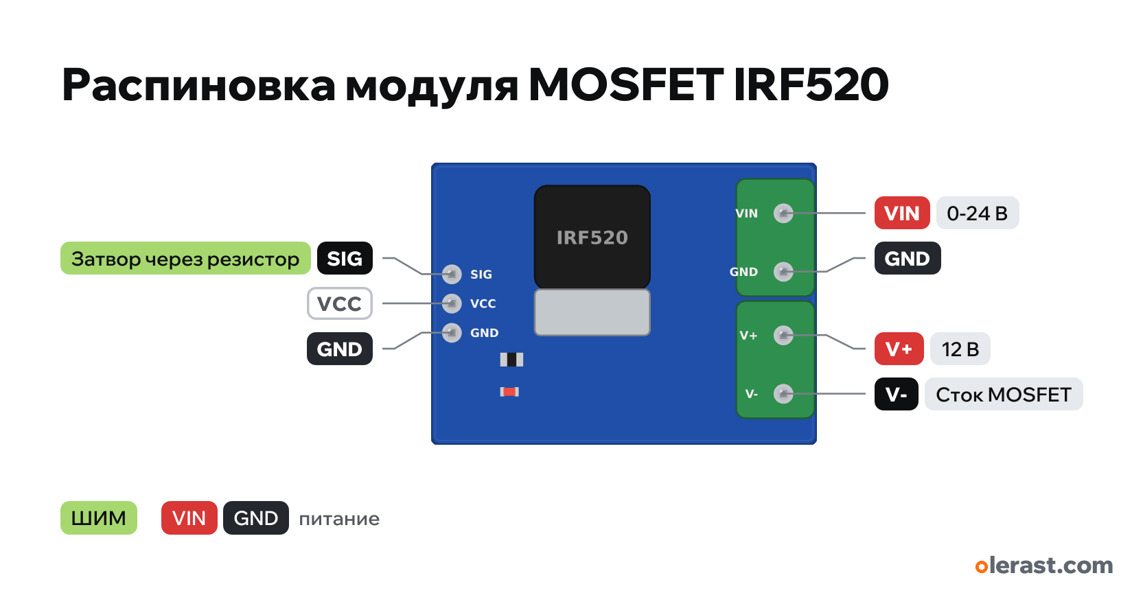
IRF520 MOSFET module pinout
IRF520 MOSFET module (SIG, VCC, GND; VIN, V+, V−), Vishay IRF520, 5 V logic, 33.5×24.5 mm, 7 pins
partly verified17.10.2026
Top view, header on the left, terminals on the right.
Download PNG- Chip
- Vishay IRF520
- Logic
- 5 V
- Power
- VIN (terminal) 0-24 V
Important
- The IRF520 is not a logic-level MOSFET: Rds(on) is specified at 10 V on the gate. From an Arduino (5 V) it handles a couple of amps with heating, from an ESP32 or Pico (3.3 V) it may not turn on at all. For 3.3 V use a module with an IRLZ44N, AO3400 or a driver with an optocoupler.
- Low-side switch: the load goes between V+ and V−, the supply negative to the terminal GND. The header GND and terminal GND are common.
- For a motor, solenoid or relay add a diode (1N4007 or 1N5819) across the load with the cathode to V+: there is none on the board.
- VCC on the header is not connected to anything.
All pins
| Label | Number | Functions | Limits | Check |
|---|---|---|---|---|
| SIG | Gate through a resistor: HIGH = load on, PWM | not from manufacturerLabels from sellers and photos, no manufacturer schematic; terminal positions are not dimensioned.Active high. At 5 V the IRF520 does not turn on fully (Rds(on) 0.27 Ω is specified only at 10 V), at 3.3 V it may not turn on at all. | ||
| VCC | not from manufacturerLabels from sellers and photos, no manufacturer schematic; terminal positions are not dimensioned.Not connected to anything on the board (ProtoSupplies): no need to supply it. | |||
| GND | Ground | not from manufacturerLabels from sellers and photos, no manufacturer schematic; terminal positions are not dimensioned. | ||
| VIN | 12 V | power input | not from manufacturerLabels from sellers and photos, no manufacturer schematic; terminal positions are not dimensioned.Positive of the load supply: connected internally to V+. | |
| GND | Ground | not from manufacturerLabels from sellers and photos, no manufacturer schematic; terminal positions are not dimensioned. | ||
| V+ | 12 V | power output | not from manufacturerLabels from sellers and photos, no manufacturer schematic; terminal positions are not dimensioned.Positive of the load: same as VIN. | |
| V- | MOSFET drain: negative of the load | not from manufacturerLabels from sellers and photos, no manufacturer schematic; terminal positions are not dimensioned.Negative of the load: connected to GND when SIG = HIGH. For a motor or coil add a diode with the cathode to V+ (there is none on the board).Labelled on other revisions as: V− |
Sources
Not verified against the manufacturer: 7 of 7 pins. The pin card says what confirms each one and where sources disagree.
- Vishay IRF520 Power MOSFET (S21-0819-Rev. C, 02-Aug-2021)datasheet, checked 17.10.2026TO-220AB G, D, S; 100 V, 9.2 A; Vgs(th) 2.0-4.0 V; Rds(on) 0.27 Ω at Vgs = 10 V
- ProtoSupplies: IRF520 N-Ch MOSFET Modulethird-party source, checked 17.10.2026SIG, VCC, GND on the header, VCC not connected; VIN, GND and V+, V− on the terminals; low-side switch, gate pull-down to GND; from 3.3 V about 1 A
Size: about 33×24 mm; terminal and header positions from the photo (approximate).
FAQ
- What supply voltage does the IRF520 MOSFET module need?
- VIN (terminal): 0-24 V. 5 V logic.