XL6009 boost module pinout
XL6009 boost module (43×21, up to 4 A switch), XL6009E1, 5 V logic, 43×21 mm, 4 pins
partly verified17.10.2026
Top view, input on the left, output on the right.
Download PNG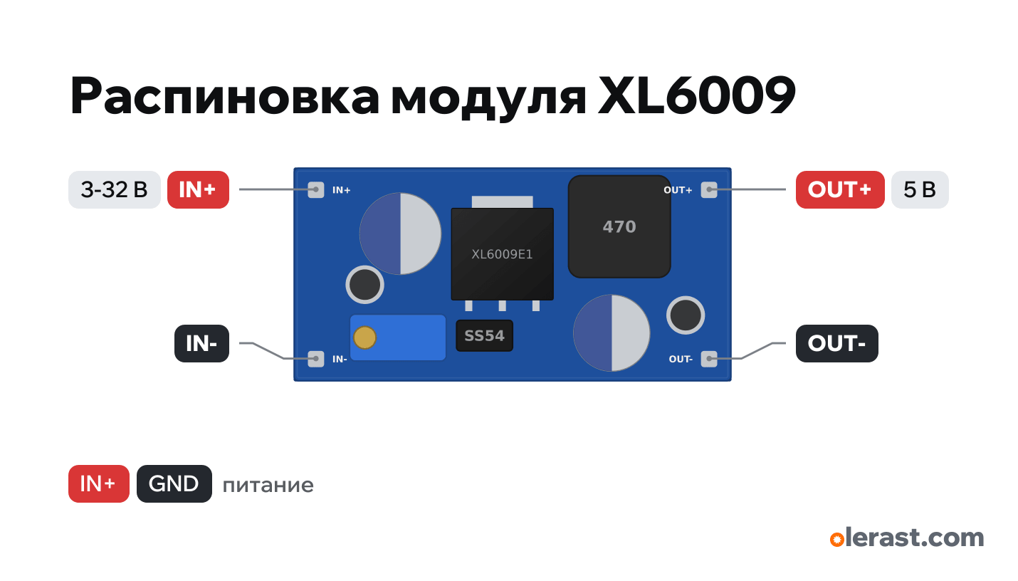
- Chip
- XL6009E1
- Logic
- 5 V
- Power
- IN+ 3-32 V
Important
- The output is adjustable: the builder and the circuit check assume 5 V. Set it with the trimmer before connecting the board, with no load, using a multimeter.
- A boost converter does not step down: an input above the output passes to the output through the diode.
- More powerful than the MT3608: 5 → 12 V about 1 A. No-load current 5–10 mA.
- Geometry from seller descriptions (±0.5 mm), components drawn approximately. Check with calipers before laying out your own board.
- Output 5–35 V set with the trimmer (5 V in the data). Output current depends on the boost ratio: 12 → 24 V about 1 A.
Revisions and clones
- Buck-boost on the XL6009 (SEPIC, blue, 48×25): can also step down, same labels.
All pins
| Label | Number | Functions | Limits | Check |
|---|---|---|---|---|
| IN+ | 5 V | power input | not verifiedWhich of the two end pads is "+" and which is "−" is not verified against the descriptions found: read the labels on the board. | |
| IN- | Ground | not verifiedWhich of the two end pads is "+" and which is "−" is not verified against the descriptions found: read the labels on the board.Common negative of input and output (connected on the board). | ||
| OUT+ | 5 V | power output | not verifiedWhich of the two end pads is "+" and which is "−" is not verified against the descriptions found: read the labels on the board.Output 5–35 V (5 V in the circuit check). | |
| OUT- | Ground | not verifiedWhich of the two end pads is "+" and which is "−" is not verified against the descriptions found: read the labels on the board. |
Sources
Not verified against the manufacturer: 4 of 4 pins. The pin card says what confirms each one and where sources disagree.
- Soldered 101600: Step-up module with XL6009 (specification, Mouser)third-party source, checked 17.10.2026In+, In−, Out+, Out−; 43×21×14 mm; input 3–32 V, output 5–35 V, 4 A switch
Size: 43×21×14 mm per Soldered and sellers (approximate).
You might also need
Similar boards
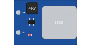
Boost module 0.9–5 V → 5 V with a USB socket (600 mA)
unmarked (boost controller, SOT-23)4 pins
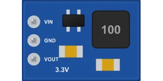
DD4012SA mini buck module, 3.3 V (up to 1 A, 3 pins)
unmarked (controller in SOT-23-6)3 pins
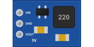
DD4012SA mini buck module for 5 V (up to 1 A, 3 pins)
unmarked (controller in SOT-23-6)3 pins
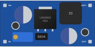
LM2596 buck module (blue 43×21, trimmer, up to 2-3 A)
LM2596S-ADJ4 pins