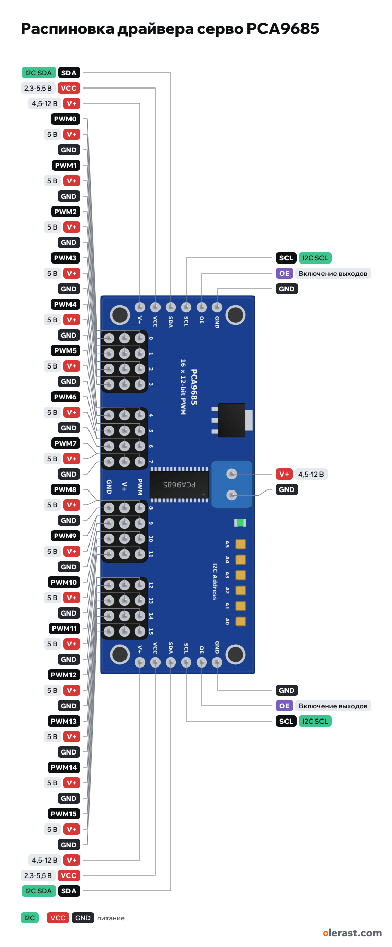
PCA9685 pinout
PCA9685, 16-servo I2C driver (Adafruit 815), NXP PCA9685, 3.3 V logic, 62.23×25.4 mm, 62 pins
verified17.10.2026
Top view, servo outputs at the bottom, terminal block at the top, rotated 90° on the diagram.
Download PNG- Chip
- NXP PCA9685
- Logic
- 3.3 V
- Power
- VCC 2.3-5.5 VV+ (terminal block) 4.5-12 V
- I2C address
- 0x40second 0x41
Important
- Address 0x40; the A0-A5 jumpers on the board add 1, 2, 4, 8, 16, 32 (0x40-0x7F). Address 0x70 (All Call) is listened to by all PCA9685 by default: do not give it to other devices.
- VCC is 3.3 or 5 V logic, V+ is servo power through the terminal block. Mixing them up burns the board.
- The frequency is shared by all 16 channels: 50 Hz for servos (Adafruit PWM Servo Driver library).
- The side rows are identical: the second one is for chaining several boards.
- Power the servos through the V+ terminal block from a separate 5-6 V supply, not from VCC.
Revisions and clones
- Clones (often marked HW-170) follow the Adafruit layout, but the electrolytic C2 may be fitted while Q1 is not.
- There is an Arduino shield on the same chip: a different module.
All pins
| Label | Number | Functions | Limits | Check |
|---|---|---|---|---|
| GND | Ground | verified | ||
| OE | Output enable: low = outputs active, high = all off | onboard pull-down | verifiedPulled to ground on the board: can be left unconnected. | |
| SCL | I2C SCL | onboard pull-up | verified10 kΩ pull-up to VCC. | |
| SDA | I2C SDA | onboard pull-up | verified10 kΩ pull-up to VCC. | |
| VCC | 3.3 V | power input | verifiedChip power and output level: 3.3 or 5 V, same as the board. | |
| V+ | 5 V | power inputpower output | verifiedServo power (5-6 V, up to 12 V). The chip is not powered from it. Do not confuse with VCC. | |
| GND | Ground | verified | ||
| OE | Output enable: low = outputs active, high = all off | onboard pull-down | verifiedPulled to ground on the board: can be left unconnected. | |
| SCL | I2C SCL | onboard pull-up | verified10 kΩ pull-up to VCC. | |
| SDA | I2C SDA | onboard pull-up | verified10 kΩ pull-up to VCC. | |
| VCC | 3.3 V | power input | verifiedChip power and output level: 3.3 or 5 V, same as the board. | |
| V+ | 5 V | power inputpower output | verifiedServo power (5-6 V, up to 12 V). The chip is not powered from it. Do not confuse with VCC. | |
| PWM0 | Channel 0: 12-bit PWM | verified220 Ω in series, level = VCC, up to 25 mA.Labelled on other revisions as: 0 | ||
| PWM1 | Channel 1: 12-bit PWM | verified220 Ω in series, level = VCC, up to 25 mA.Labelled on other revisions as: 1 | ||
| PWM2 | Channel 2: 12-bit PWM | verified220 Ω in series, level = VCC, up to 25 mA.Labelled on other revisions as: 2 | ||
| PWM3 | Channel 3: 12-bit PWM | verified220 Ω in series, level = VCC, up to 25 mA.Labelled on other revisions as: 3 | ||
| V+ | 5 V | power output | verifiedServo power: common V+ rail. | |
| V+ | 5 V | power output | verifiedServo power: common V+ rail. | |
| V+ | 5 V | power output | verifiedServo power: common V+ rail. | |
| V+ | 5 V | power output | verifiedServo power: common V+ rail. | |
| GND | Ground | verified | ||
| GND | Ground | verified | ||
| GND | Ground | verified | ||
| GND | Ground | verified | ||
| PWM4 | Channel 4: 12-bit PWM | verified220 Ω in series, level = VCC, up to 25 mA.Labelled on other revisions as: 4 | ||
| PWM5 | Channel 5: 12-bit PWM | verified220 Ω in series, level = VCC, up to 25 mA.Labelled on other revisions as: 5 | ||
| PWM6 | Channel 6: 12-bit PWM | verified220 Ω in series, level = VCC, up to 25 mA.Labelled on other revisions as: 6 | ||
| PWM7 | Channel 7: 12-bit PWM | verified220 Ω in series, level = VCC, up to 25 mA.Labelled on other revisions as: 7 | ||
| V+ | 5 V | power output | verifiedServo power: common V+ rail. | |
| V+ | 5 V | power output | verifiedServo power: common V+ rail. | |
| V+ | 5 V | power output | verifiedServo power: common V+ rail. | |
| V+ | 5 V | power output | verifiedServo power: common V+ rail. | |
| GND | Ground | verified | ||
| GND | Ground | verified | ||
| GND | Ground | verified | ||
| GND | Ground | verified | ||
| PWM8 | Channel 8: 12-bit PWM | verified220 Ω in series, level = VCC, up to 25 mA.Labelled on other revisions as: 8 | ||
| PWM9 | Channel 9: 12-bit PWM | verified220 Ω in series, level = VCC, up to 25 mA.Labelled on other revisions as: 9 | ||
| PWM10 | Channel 10: 12-bit PWM | verified220 Ω in series, level = VCC, up to 25 mA.Labelled on other revisions as: 10 | ||
| PWM11 | Channel 11: 12-bit PWM | verified220 Ω in series, level = VCC, up to 25 mA.Labelled on other revisions as: 11 | ||
| V+ | 5 V | power output | verifiedServo power: common V+ rail. | |
| V+ | 5 V | power output | verifiedServo power: common V+ rail. | |
| V+ | 5 V | power output | verifiedServo power: common V+ rail. | |
| V+ | 5 V | power output | verifiedServo power: common V+ rail. | |
| GND | Ground | verified | ||
| GND | Ground | verified | ||
| GND | Ground | verified | ||
| GND | Ground | verified | ||
| PWM12 | Channel 12: 12-bit PWM | verified220 Ω in series, level = VCC, up to 25 mA.Labelled on other revisions as: 12 | ||
| PWM13 | Channel 13: 12-bit PWM | verified220 Ω in series, level = VCC, up to 25 mA.Labelled on other revisions as: 13 | ||
| PWM14 | Channel 14: 12-bit PWM | verified220 Ω in series, level = VCC, up to 25 mA.Labelled on other revisions as: 14 | ||
| PWM15 | Channel 15: 12-bit PWM | verified220 Ω in series, level = VCC, up to 25 mA.Labelled on other revisions as: 15 | ||
| V+ | 5 V | power output | verifiedServo power: common V+ rail. | |
| V+ | 5 V | power output | verifiedServo power: common V+ rail. | |
| V+ | 5 V | power output | verifiedServo power: common V+ rail. | |
| V+ | 5 V | power output | verifiedServo power: common V+ rail. | |
| GND | Ground | verified | ||
| GND | Ground | verified | ||
| GND | Ground | verified | ||
| GND | Ground | verified | ||
| V+ | 5 V | power input | verifiedServo power input. | |
| GND | Ground | verified |
Sources
Every pin is verified against the manufacturer's documents.
- Adafruit: Adafruit PCA9685 rev C.brd (Eagle)board drawing, checked 17.10.2026outline 62.23×25.4; side rows GND, OE, SCL, SDA, VCC, V+ at x 1.905 and 60.325; 4 output groups 3×4 (PWM, V+, GND) at y 18.92-24.0; V+/GND terminal block 3.5 pitch; jumpers A0-A5; Q1 AOD417; 220 Ω resistors
- Adafruit Learn: 16-Channel PWM/Servo Driver, Pinoutsuser guide, checked 17.10.2026VCC 3-5 V (logic and 10 kΩ pull-ups), V+ 5-6 V up to 12 V, OE active low and pulled to ground, 220 Ω on the outputs, 25 mA per pin, address 0x40
- Adafruit: 16-Channel 12-bit PWM/Servo Driver - I2C (815)user guide, checked 17.10.202662.5×25.4 mm, 6-bit address jumpers, chain of up to 62 boards
- NXP PCA9685 datasheet (Adafruit copy)datasheet, checked 17.10.2026supply 2.3-5.5 V, inputs and outputs tolerate 5.5 V, current 6 mA (up to 10), 2.2 µA in sleep mode, address 1 A5...A0, LED All Call
Size: per the Eagle outline.
FAQ
- What is the I2C address of the PCA9685?
- 0x40. The second address is 0x41: solder the A0 jumper on the board (A0-A5 give addresses 0x40-0x7F). SDA and SCL pull-ups are on the module.
- What supply voltage does the PCA9685 need?
- VCC: 2.3-5.5 V; V+ (terminal block): 4.5-12 V. 3.3 V logic.