USB-C 16P breakout to pins pinout
USB-C 16P breakout to pins (VBUS, GND, CC1, CC2, D+, D−), USB Type-C 16P receptacle (USB 2.0), 3.3 V logic, 18×14 mm, 6 pins
partly verified17.10.2026
Top view, USB-C receptacle at the top, row of pins at the bottom.
Download PNG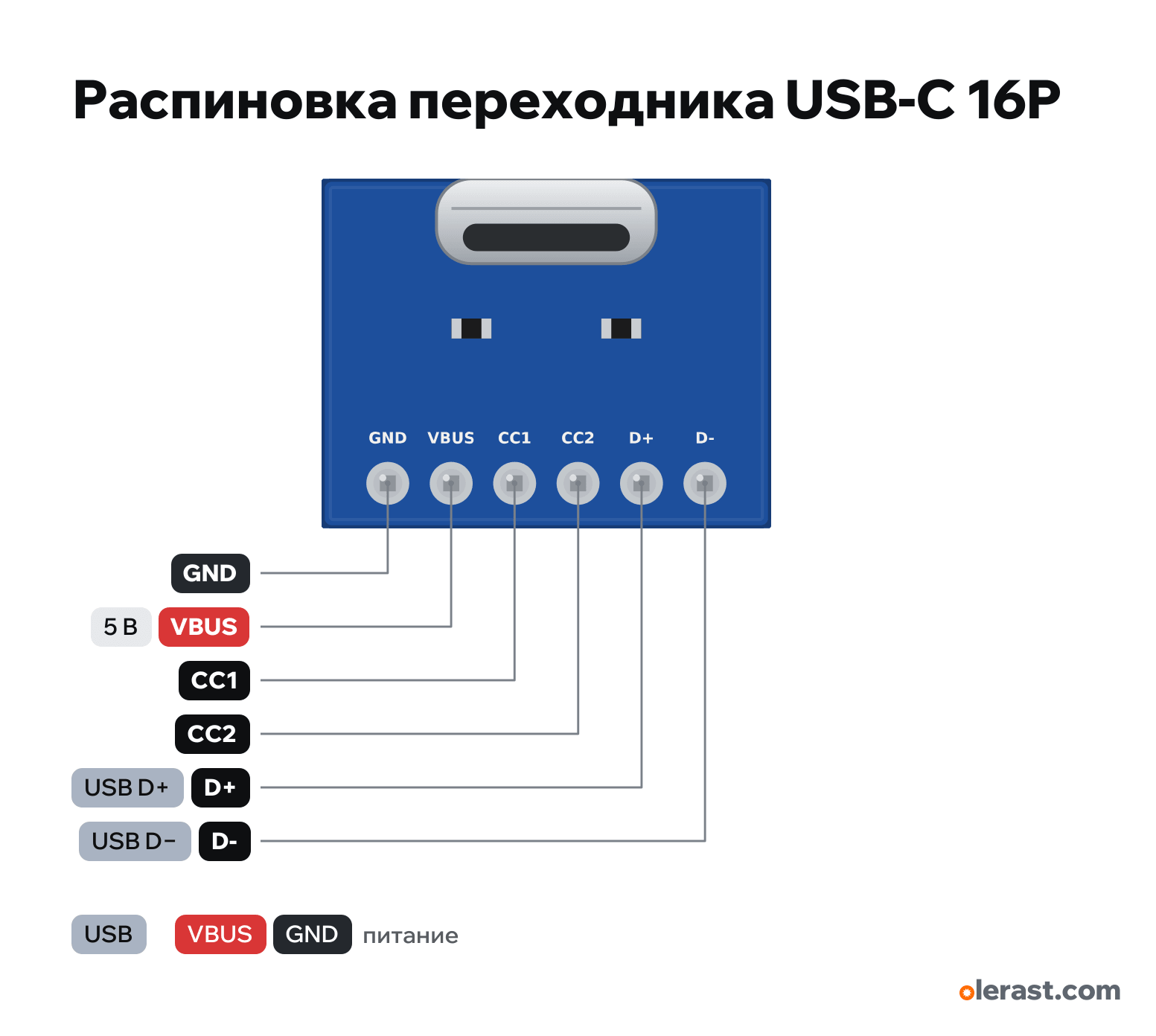
- Chip
- USB Type-C 16P receptacle (USB 2.0)
- Logic
- 3.3 V
- Power
- USB-C 4.75-5.25 V
Important
- For your own boards with USB (RP2040, ESP32-S3, CH340): D+ and D− to the chip, CC1 and CC2 through 5.1 kΩ to ground.
- If the board has no resistors on CC, a USB-C charger (C-C cable) will supply no power.
- VBUS current is up to 3 A by the standard, up to 1.5-2 A on cheap connectors.
- 5 V from USB. A USB-C source (charger, power bank, laptop) enables VBUS only if 5.1 kΩ resistors from CC1 and CC2 to ground are present.
Revisions and clones
- 24P (full connector, with SBU and USB 3 lines): the same VBUS, GND, CC, D+/D− plus extra pins.
All pins
| Label | Number | Functions | Limits | Check |
|---|---|---|---|---|
| GND | Ground | not verifiedUnbranded adapter: labels and pad order differ between boards and are not verified. Read the labels on your board. | ||
| VBUS | 5 V | power output | not verifiedUnbranded adapter: labels and pad order differ between boards and are not verified. Read the labels on your board.5 V from USB. A USB-C source (charger, power bank, laptop) enables VBUS only if 5.1 kΩ resistors from CC1 and CC2 to ground are present.Labelled on other revisions as: VCC, 5V | |
| CC1 | CC1: to ground through 5.1 kΩ (if the resistor is on the board) | not verifiedUnbranded adapter: labels and pad order differ between boards and are not verified. Read the labels on your board.If the board has no resistors, add 5.1 kΩ from CC1 and from CC2 to GND, otherwise a USB-C charger will not give 5 V. | ||
| CC2 | CC2: to ground through 5.1 kΩ | not verifiedUnbranded adapter: labels and pad order differ between boards and are not verified. Read the labels on your board. | ||
| D+ | USB D+ | not verifiedUnbranded adapter: labels and pad order differ between boards and are not verified. Read the labels on your board.USB 2.0 data (3.3 V). The connector has two D+/D− pairs, joined on the board.Labelled on other revisions as: DP | ||
| D- | USB D− | not verifiedUnbranded adapter: labels and pad order differ between boards and are not verified. Read the labels on your board.Labelled on other revisions as: DN, D− |
Sources
Not verified against the manufacturer: 6 of 6 pins. The pin card says what confirms each one and where sources disagree.
- USB Type-C Cable and Connector Specification (USB-IF), Rd 5.1 kΩ on CC on the consumer sidedatasheet, checked 17.10.2026the consumer (Sink) places Rd 5.1 kΩ from CC1 and CC2 to ground, without it a USB-C source does not enable VBUS; D+/D− as in USB 2.0
Size: not dimensioned, about 18×14 mm (approximate).
You might also need
Similar boards
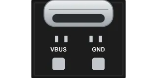
USB-C power-only breakout (6P connector, VBUS and GND, 5.1 kΩ resistors)
USB Type-C 6P socket (VBUS ×2, GND ×2, CC1, CC2)2 pins
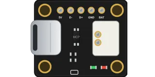
Adafruit Micro-Lipo USB-C LiPo charger (MCP73831, product 4410)
MCP73831T-2ACI/OT7 pins
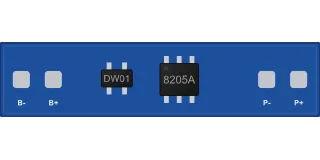
BMS 1S protection board (3.7 V, DW01 + 8205A)
DW01A + FS8205A4 pins
BMS 2S protection board (7.4 V, with balancing)
2S protection controller (HY2120/HY2213 and equivalents) + MOSFET5 pins